-
From Wikipedia, the free encyclopedia
A time-of-flight camera (TOF camera) is a camera system that creates distance data with help of the time-of-flight (TOF) principle. The scene is illuminated by short light pulses and the camera measures the time taken until the reflected light reaches the camera again. This time is directly proportional to the distance. The camera therefore provides a range value for each pixel. The principle is similar to that of 3D scanners with the advantage that whole scene is captured at the same time.
Time-of-flight cameras are relatively new devices, as the semiconductor processes have only recently become fast enough for such devices. The systems cover ranges of a few metres up to about 40 m. The distance resolution is about 1 cm, and the lateral resolution is about 200 by 200 pixels. The biggest advantage of the cameras may be that they provide up to 100 images per second.
Setup
A time-of-flight camera consists of the following components:
- Illumination unit: It illuminates the scene. As the light has to be modulated with high speeds up to 100 MHz, only LEDs or Laser diodes are feasible. The illumination normally uses infrared light to make the illumination unobtrusive.
- Optics: A lens gathers the reflected light and images the environment onto the image sensor. An optical band pass filter only passes the light with the same wavelength as the illumination unit. This helps suppress background light.
- Image sensor: This is the heart of the TOF camera. Each pixel measures the time the light has taken to travel from the illumination unit to the object and back. The image sensor is built up similar to other image sensors except for the pixel, which is much more complicated. It contains two or more fast shutters to sample the incoming light at given points in time. Because of this functionality, TOF pixels, in contrast to pixels in current 2D digital cameras, have large pixel sizes up to 100 micrometers.
- Driver electronics: Both the illumination unit and the image sensor have to be controlled by high speed signals. These signals have to be very accurate to obtain a high resolution. For example, if the signals between the illumination unit and the sensor shift by only 10 picoseconds, the distance changes by 1.5 mm. For comparison: current CPUs reach frequencies of up to 3 GHz, corresponding to clock cycles of about 300 ps - the corresponding 'resolution' is only 45 mm.
- Computation/Interface: The distance is calculated directly in the camera. To obtain good performance, some calibration data is also used. The camera then provides a distance image over a USB or Ethernet interface.
Principle
The simplest version of a time-of-flight camera uses light pulses. The illumination is switched on for a very short time, the resulting light pulse illuminates the scene and is reflected by the objects. The camera lens gathers the reflected light and images it onto the sensor plane. Depending on the distance, the incoming light experiences a delay. As light has a speed of c = 300,000,000 meters per second, this delay is very short: an object 2.5 m away will delay the light by:

The pulse width of the illumination determines the maximum range the camera can handle. With a pulse width of e.g. 50 ns, the range is limited to

These short times show that the illumination unit is a critical part of the system. Only with some special LEDs or lasers is it possible to generate such short pulses.
The single pixel consists of a photo sensitive element (e.g. a photo diode). It converts the incoming light into a current. Connected to the photo diode are fast switches, which direct the current to one of two (or several) memory elements (e.g. a capacitor) that act as summation elements. In the diagram, the pixel uses two switches (G1 and G2) and two memory elements (S1 and S2). The switches are controlled by a pulse with the same length as the light pulse, where the control signal of switch G2 is delayed by exactly the pulse width. Depending on the delay, only part of the light pulse is sampled through G1 in S1, the other part is stored in S2. Depending on the distance, the ratio between S1 and S2 changes as depicted in the drawing. Because only small amounts of light hit the sensor within 50 ns, not only one but several thousands pulses are sent out (repetition rate tR) and gathered, thus increasing the signal to noise ratio.
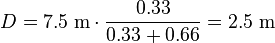
After the exposure, the pixel is read out and the following stages measure the signals S1 and S2. As the length of the light pulse is defined, the distance can be calculated with the following formula:

In the example, the signals have the following values: S1 = 0.66 und S2 = 0.33. The distance is therefore:
In the presence of background light, the memory elements receive an additional part of the signal. This would disturb the distance measurement. To eliminate the background part of the signal, the whole measurement can be performed a second time with the illumination switched off. If the objects are further away than the distance range, the result is also wrong. Here, a second measurement with the control signals delayed by an additional pulse width helps to suppress such objects. Other systems work with a sinusoidally modulated light source instead of the pulse source.
(see also time-of-flight)
Advantages
Simplicity
In contrast to stereo vision or triangulation systems, the whole system is very compact: the illumination is placed just next to the lens, whereas the other systems need a certain minimum base line. In contrast to laser scanning systems, no mechanical moving parts are needed.
Efficient distance algorithm
It is very easy to extract the distance information out of the output signals of the TOF sensor, therefore this task uses only a small amount of processing power, again in contrast to stereo vision, where complex correlation algorithms have to be implemented. After the distance data has been extracted, object detection, for example, is also easy to carry out because the algorithms are not disturbed by patterns on the object.
Speed
Time-of-flight cameras are able to measure the distances within a complete scene with one shot. As the cameras reach up to 100 frames per second, they are ideally suited to be used in real-time applications.
Disadvantages
Background light
Although most of the background light coming from artificial lighting or the sun is suppressed, the pixel still has to provide a high dynamic range. The background light also generates electrons, which have to be stored. For example, the illumination units in today's TOF cameras can provide an illumination level of about 1 watt. The Sun has an illumination power of about 50 watts per square meter after the optical bandpass filter. Therefore, if the illuminated scene has a size of 1 square meter, the light from the sun is 50 times stronger than the modulated signal.
Interference
If several time-of-flight cameras are running at the same time, the cameras may disturb each others' measurements. There exist several possibilities for dealing with this problem:
- Time multiplexing: A control system starts the measurement of the individual cameras consecutively, so that only one illumination unit is active at a time.
- Different modulation frequencies: If the cameras modulate their light with different modulation frequencies, their light is collected in the other systems only as background illumination but does not disturb the distance measurement.
Multiple reflections
In contrast to laser scanning systems, where only a single point is illuminated at once, the time-of-flight cameras illuminate a whole scene. Due to multiple reflections, the light may reach the objects along several paths and therefore, the measured distance may be greater than it actually is.
'Colour|Image > Image_Sensor' 카테고리의 다른 글
Chromatic Aberration (색수차) (0) 2010.05.11 Active Pixel Sensor (0) 2009.08.04 FinePix REAL 3D Technology Debut (0) 2009.07.27


